Shielding Receivers
Transmission Characteristics
The transmission frequency of DSI transmitters is 455 KHz. The range of susceptibility is approximately 400 to 500 KHz. Very strong signals slightly outside of this range may have an effect as well. Radio waves at frequencies outside this range generally will not directly interfere with the telemetry signal. However, some sources may contain stray frequencies that fall in this frequency range. For example, a 50 Hz or 60 Hz power line may (and often does) have harmonics that cause interference in this frequency range. These can be heard as a buzz or static on an AM radio.
As we have a relatively short transmission range, most of our signal is magnetically coupled from the transmitter to the receiver antennae. DSI receivers are somewhat susceptible to strong electric field and plane wave signals from other sources. These sources may include fluorescent lights, large motors or other electric devices, and also radio stations. In most cases these are not problematic and can be minimized by relocating or shielding the telemetry area.
The sensitivity of DSI RPC-1 receivers is listed below. This measurement is taken with a 9 kHz / 6 dB bandwidth receiver. This measurement may only be helpful if the level of interference outside the room is known:
- 61 dB μV/m (dB above 1 microvolt per meter) - electric field measurement used in US and Canada (converted from the magnetic field measurement below)
- 10 dB μA/m (dB above 1 microamp per meter) - magnetic field measurement used in Europe (the field sensed by the receiver is primarily magnetic field)
A level of 30dB attenuation would typically be more than adequate to block external noise generated by utilities within the walls of the lab space.
Shielding Considerations
There are two primary shielding concerns—electric shielding and magnetic shielding. These can generally be accommodated with a single material such as stainless steel or copper. Copper provides the best possible electric shielding (due to its high conductivity), but is very expensive. It is common to use copper mesh or screening rather than a solid copper sheet or panel. Stainless steel panels also work very well.
There is some level of concern about the “quietness” of the room itself. An electrically “noisy” room is generally a larger concern in older buildings that don't provide a good ground to the electrical wiring. A noisy environment may also result from the presence of a large electric device (such as an MRI or fluoroscope) either from direct emissions or from disruption of the power lines. The first course of action is to provide a good ground for electrical wiring and for all major electrical devices. It can be helpful to provide conductive screening in the walls, floor and/or ceiling. In the ideal situation, these would all be tied together at the seams and would be connected to a very good quality ground source. We don't necessarily recommend going to this extreme unless it is known that a problem exists or might be expected to exist in a new building. It is best to try to isolate major electrical devices on a separate ground from that used in the telemetry setup if possible.
The more common situation would be to provide shielding in the immediate cage area. The most common sources of noise and interference are nearby electrical wiring and other telemetry transmitters. These both have a limited range and are generally considered “near field” sources. For example, if you would like to minimize the spacing between cages and receivers, you might choose to use conductive screen or panels between the cages. The best case is to have all six sides shielded. However, this is obviously not practical in most situations.
Typical Cage Shielding
There are a number of ways to shield cages to prevent electromagnetic noise interference in the data. Shielding can be used around individual animal cages and/or MX2s. If possible, additional shielding should be used when configuring the animal room. Shielding is highly recommended when non-metal shelves are used. You can estimate the range of the transmitter by finding the longest range of reception from the receiver and drawing an imaginary arc around the transmitter body. The height of the shield and distance from the cage should be such that the imaginary arc can't exceed the top/bottom/front/back of the shielding panel, and that the imaginary arc won't reach a receiver on the opposite side of the shielding panel.
If the shelving is metal, it is best to have the shielding in direct contact with the shelf to prevent the signal from going under the paneling to the next receiver.
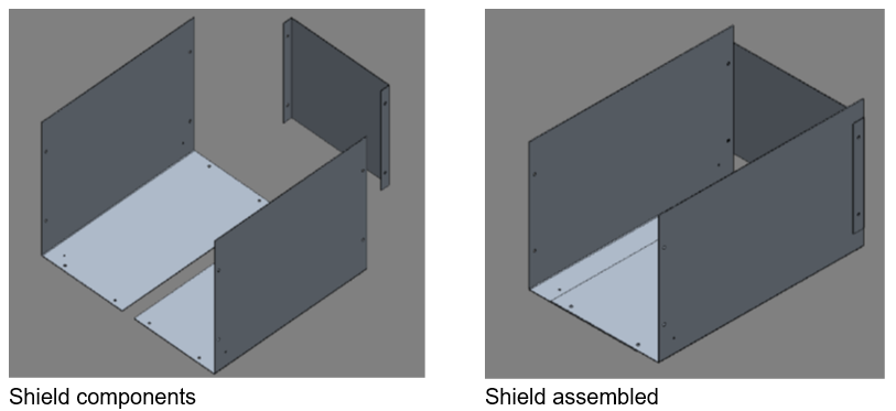
The shielding material should consist of conductive metal such as copper, stain-less steel, or aluminum. As shown below, shielding allows cages to be placed closer together.
Note: The shields can be constructed in such a manner that the following four configurations can be achieved (length x width x height):
- 18 x 12 x 10 inches
- 18 x 12 x 12 inches
- 18 x 18 x 10 inches
- 18 x 18 x 12 inches
In large animal cage installations, it is often not possible or practical to provide shielding under the cage. This causes a limitation in how close adjacent telemetry cages can be. In the worst case, a dog in cage #1 may be lying against the wall immediately opposite the receiver in cage #2, while the dog of interest in cage #2 is in the back of the cage. In this case, it is entirely possible that the telemetry signal registered from cage #2 is actually coming from the dog in cage #1 and will provide incorrect and misleading results.
Practical Diagnostics
In any case, the best diagnostic tool to understand the characteristics of the transmitter/receiver and the room environment is the AM radio tuned to the lowest end of the band. This should provide a wealth of information regarding a given system setup and the considerations you might make when designing a new room. This can be used to detect noise sources as well as to assess the likelihood of interference between cages. If you are using RMC-1 or RPC-1 receivers with Dataquest A.R.T., the signal strength is also a useful diagnostic tool. The lowest valid signal strength is 17 and the strongest signal strength depends on the transmitter model. Generally a signal strength over 20 will provide very reliable signals, provided that there is not also a presence of a strong interference signal.
Comments
0 comments
Please sign in to leave a comment.