Understanding Cycle Timing with Pulmonary Air Flow (PAF) Module
The following diagrams and figures can be used to understand how the Ponemah PAF analysis module calculates the various timing intervals for a breathing cycle.
Cycle 19 will be used in the figures that follow. It is important to not that a PAF cycle begins with the Start Inspiration Mark.
Figure 1 provides a visual representation of the fiducial marks used to mark the key points of interest in a cycle and how the are used to obtain the total cycle time.
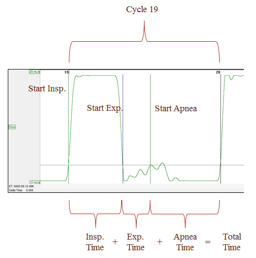
Figure 1
Figure 2 displays the Ponemah Derived List View containing Cycle 19 and the derived calculations for this cycle.

Figure 2
Using Ponemah's Delta Time feature, Figures 3 through 6 display the time, in seconds, between each marker. These should be equal to the Ponemah derived calculations. In Figure 3, we will start with the curson on the Start Inspiration mark of Cycle 19.
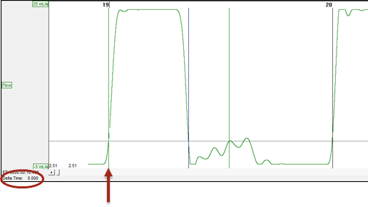
Figure 3
After a reset of the Delta Time was performed, the cursor was placed on the Start Expiration mark, as displayed in Figure 4. This provides the Inspiratory Time (IT).
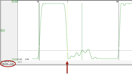
Figure 4
After a reset of the Delta Time was performed, the cursor was placed on the Start Apnea mark, as displayed in Figure 5. This provides the Expiratory Time (ET).
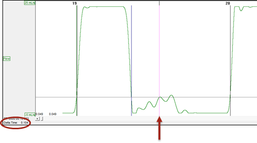
Figure 5
After a reset of the Delta Time was performed, the cursor was placed on the Start Inspiration mark of Cycle 20, as displayed in Figure 6. This provides the Apnea Time (AT)
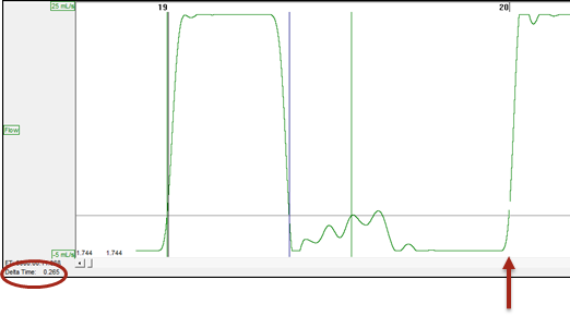
Figure 6
In Figure 7, the cursor was placed on the Start Inspiration mark of Cycle 19, a reset Delta Time action was performed, and then the cursor was placed on the Start Inspiration mark of Cycle 20. This provides the Total Time (TT).
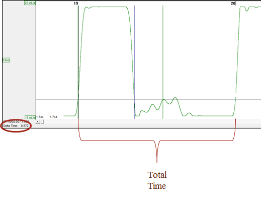
Figure 7
Comments
0 comments
Please sign in to leave a comment.